Pushing the frontiers of automotive fuel cell design

Technician Brad Ross prepares a sample for use with the FEI Tecnai G2 200kV TEM
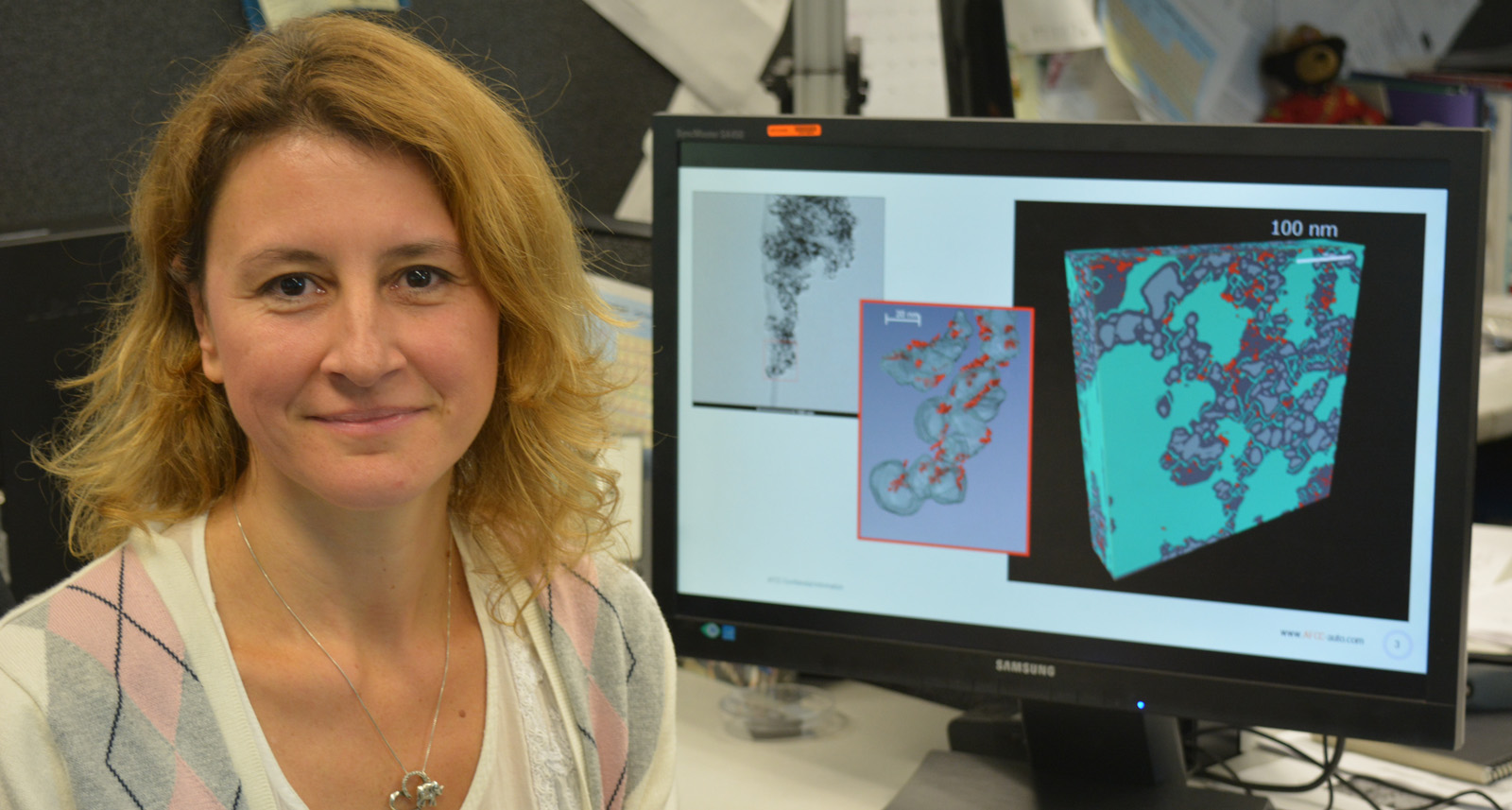
Reducing the use of expensive catalyst materials is vital in developing the next generation of commercially viable fuel cells for vehicles. Dr. Jasna Jankovic of the Automotive Fuel Cell Cooperative Corp. partnered with UBC’s Imaging Lab facilities to visualize and understand the 3D distribution of platinum catalyst particles and other crucial components within fuel cells. By accessing the expert training, assistance and advice of UBC’s technicians and researchers, Dr. Jankovic was able to use the Transmission Electron and Scanning Electron Microscopes to peek into the secrets of the 3D nano-world in order to develop high-performing fuel cells at a significantly lower cost. Dr. Jasna Jankovic, a research scientist with the Automotive Fuel Cell Cooperative Corp. (AFCC) in Burnaby, British Columbia, led a research project at the Bioimaging Facility (BIF), part of UBC Imaging Labs, in which she used the FEI Tecnai G2 200kV Transmission Electron Microscope (TEM) to reveal and better understand the 3D distribution of platinum catalyst particles and other components in the catalyst layer of proton exchange membrane (PEM) fuel cells. The performance and durability of fuel cells greatly depend on the fuel cell electrode catalyst layers and their composition. “Catalyst layers, where all electrochemical reactions happen and current is produced, contain pores, carbon particles, platinum catalyst particles and a polymer network. The distribution of all these components in the catalyst layer plays a major role in how a fuel cell will function and information about their 3D distribution can help explain a number of properties and the performance of a fuel cell,” explains Dr. Jankovic. The project was initiated by Dr. Darija Susac, Senior Research Scientist, Team Lead, Research and Development, who recognized the potential of the 3D electron tomography TEM technique for AFCC. New window into catalyst layer microstructure A key goal of the project was to show how the 3D electron tomography TEM technique could be used to provide valuable new information and a realistic picture of the spatial distribution of each of the components in the catalyst layer at the nanoscale level, which could not be obtained using other methods such as 2D imaging or 3D imaging using SEM (scanning electron microscopy). The technique could then potentially be used in future studies to help improve catalyst layer and fuel cell design. In this study, Dr. Jankovic used the FEI Tecnai TEM instrument to image and then reconstruct 3D models of three types of commercially available platinum catalysts deposited on three types of carbon supports. “The project helped us reveal the differences between the microstructure of carbon supports and platinum catalyst distribution for three different fuel cell catalysts. With 3D electron tomography, we could see much better how the platinum catalyst particles are actually distributed. These findings helped us understand the nature of these catalysts and this technique could be useful in designing an optimal distribution of platinum catalyst for better fuel cell performance,” explains Dr. Jankovic. Advancing commercialization of fuel cell technology This research is important in helping AFCC to advance its primary goal of commercializing fuel cell technology for automotive applications. Dr. Jankovic is now using 3D electron tomography as a cutting-edge tool to help the company design more effective fuel cells at reduced cost to be competitive with traditional power sources. “AFCC is committed to the commercialization of automotive fuel cells. This means further improving the efficiency and durability of fuel cells, while at the same time reducing the cost. Platinum catalyst is one of the main drivers of the cost, so we want to lower the amount of platinum in the catalyst layers. If we learn how platinum catalyst is really distributed in the catalyst layers, its relation to other phases in the catalyst layer, and how it affects the performance of a fuel cell, we will be able to design more effective catalyst layers at a lower cost. 3D electron tomography is enabling us to do exactly that,” says Dr. Jankovic. Expert training and support for users The Bioimaging Facility has a team of technical staff with specialized expertise in operating the FEI Tecnai TEM microscope and a wide variety of other imaging equipment to support industry and university researchers. Microscopy technician Brad Ross and his colleagues trained Dr. Jankovic to use the instrument, prepare and section the fuel cell membrane samples, collect and process the tomographic data, perform 3D volume reconstruction using FEI Inspect 3D software, and do data modeling, 3D rendering and measuring of individual components using AMIRA software. Dr. Jankovic had ready access to staff who provided the vital training and support needed for her to carry out all of the steps to meet the project’s goals. “The value of the training was huge and you need to learn how to do this from experts. The training that I received from Brad was crucial in using the instrument, and for data acquisition and processing. I had a lot of help from Derrick Horne, the electron microscopy technician, in sample preparation. My lengthy discussions with Garnet Martens, the research manager, were really useful as well in helping me improve my reconstruction approaches. Interestingly, researchers at the Bioimaging Facility mostly deal with biological samples and I was the first researcher to use their equipment for fuel cell samples. We all learned from each other in the later stages of the project,” she says. In this project, three types of commercially available, carbon-supported platinum catalysts were investigated. TEM imaging and electron tomography were carried out using the FEI Tecnai G2 Transmission Electron Microscope, with 200k acceleration voltage. Basic TEM imaging was used for general viewing and selection of an appropriate area for tomography. Electron tomography was done at 80,000x magnification and a series of micrographs was recorded by an FEI Eagle 4k CCD camera in the range of tilt angles from +70º to -70º, at an interval of 1º. FEI Inspect 3D software was used for tomography data processing and 3D volume reconstruction. A combination of Fiji Image J and Amira software was used to build and visualize the 3D models of the catalysts, and to calculate carbon and platinum surface areas and volumes, the extent of carbon support coverage with platinum, as well as platinum particle size distribution. Dr. Jasna Jankovic of the Automotive Fuel Cell Cooperative Corp. 3D nano-view helps explain key differences in catalysts Dr. Jankovic’s investigation using the FEI Tecnai TEM provided not only a rich visual characterization of the catalyst powders but also useful and detailed quantitative information about catalyst particle distribution, size and available surface area. “It’s amazing how different an understanding you can obtain once you go 3D. The 3D electron tomography technique offers imaging on a nano-level in an electron-transparent mode, enabling us to distinguish platinum catalyst particles from carbon support and pores. It enabled us to reveal the morphology of the three analyzed catalyst powders, which was very different for each one. Further analysis of the 3D models also resulted in various parameters, such as platinum catalyst and carbon particle size, distribution and coverage. This knowledge helped us explain some differences that we see in the properties and performance of these catalysts,” explains Dr. Jankovic. She and her AFCC colleagues reported their research results in an article entitled, “Electron Tomography Based 3D Reconstruction of Fuel Cell Catalysts,” in ECS Transactions, a publication of The Electrochemical Society. The training Dr. Jankovic received and the experience she gained using 3D electron tomography to investigate fuel cell catalyst powders commonly used in catalyst layers allowed her to apply the technique independently in subsequent studies at the BIF. “It was satisfying to work with Jasna on this project because we helped AFCC get the results they needed, and the company was happy with results they might not otherwise been able to get without using our facility and the FEI Tecnai TEM microscope,” says Brad Ross. “Jasna eventually became fully independent using the microscope, and doing the 3D reconstruction and modelling. After becoming proficient in these techniques, she spent a lot of time on her own working through various samples on other projects. Our goal is to train researchers to the point where they become integrated users so they can do all their work on their own with support from us as needed.” Combining TEM and SEM for complementary imaging of catalyst layers Dr. Jankovic and an AFCC research colleague also used another instrument – the FEI Helios NanoLab 650 DualBeam Scanning Electron Microscope (DB-SEM) – at the Centre for High Throughput Phenogenomics (CHTP), part of UBC Imaging Labs, to help investigate and characterize fuel cell catalyst layers. While the TEM reveals distribution of the catalyst layer components in a transmission mode, the SEM reveals the surface morphology of the layers. An advanced feature of the instrument is the combined use of the focused ion beam (FIB) and SEM mode, whereby the SEM is used to image the remaining surface of the specimen after a defined thickness has been removed by FIB. Each acquired image can be processed to create a 3D representation of the sample and viewed at any orientation, enabling 3D reconstruction of the material that can be used for visualization of the catalyst layer microstructure or modeling of the properties. This correlative workflow approach allows 3D imaging of unlimited sample thickness without the missing wedge artifact associated with tomography but at a slightly lower resolution (albeit 1-2 nm). “Dr. Gethin Owen [Technical Director of electron microscopy CHTP] was crucial in training me and my colleagues to use the instrument and helped us in every step of the analysis of challenging samples. A real benefit is obtained when the 3D SEM FIB approach is combined with the 3D electron tomography approach, as the two techniques nicely complement each other, providing the complete representation of the sample in question at high resolution,” says Dr. Jankovic. Tool to help design and build better fuel cells After showing that 3D electron tomography could provide a new and better understanding of the microstructure of fuel cell catalyst layers, Dr. Jankovic and her AFCC colleagues began using the FEI Tecnai TEM as a tool in subsequent studies to model catalyst layers of various compositions, and then simulate and compare the performance of different catalyst layer designs. “There is great potential for use of this technique. Catalyst layers can be 3D imaged, their 3D models reconstructed and using advanced modeling approaches, properties and performance of different catalyst layers designs can be predicted or optimized. The designs that perform best could then be built into real fuel cells and tested. It’s exciting to be at the forefront of this research. I feel privileged to be able to peek into the secrets of the 3D nano-world and apply this knowledge to developing new products in the real world,” says Dr. Jankovic.